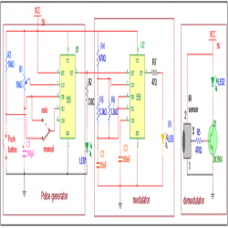
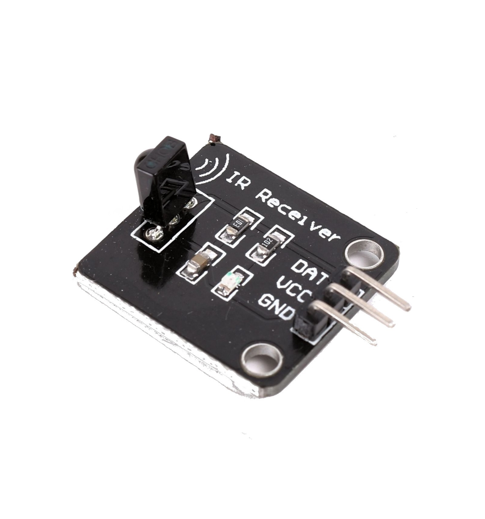
The Infra Red signals are widely used in wide range of remote control applications so it is worthy to know about the transmission and receiving the IR signals.Here the above circuit was a simple Infrared receiver circuit constructed using IC 555 and TSOP1738.The TSOP1738 was nothing but a simple IR detector used widely and here it was used for the same detecting purpose and then the signal was fed into the IC 555 which was wired as monostable multivibrator.Lets move in to the working of the above circuit.
WORKING OF INFRARED RECEIVER CIRCUIT:

In this above circuit the TSOP1738 forms the main constituent of this circuit and this was designed to detect the IR signals from any source.This was used to detect the signals of the range of 38 KHz and thus named as “TSOP1738” and last two numbers of each of this TSOP series was named for their receiving frequency range.The pin configuration was given below.
The Vs was connected to 5v power supply and the GND to ground respectively.And the output was taken from the OUT pin.The TSOP gives high signal as output in the absence of detection of any IR signals and low output whenever IR signals incident on TSOP1738.This logic was used in the above receiver circuit to to detect the Infra red signals.
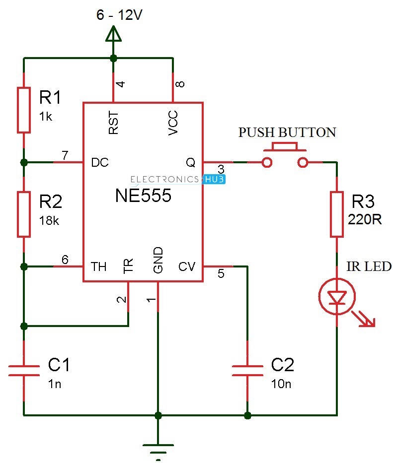
TSOP 1738 IR sensor module responds to only 38kHz pulsed infrared rays. It will not sense continuous IR ray from the IR LED.So a transmitter circuit(as one in TV remote handset) based on 555 IC is required. Any standard transmitter circuit based on 555 IC can be used. But its output should be 38kHz exactly. I noticed that the TSOP2238 I'm using can receive IR pulse from standard remote control (15 meters easily approx 49ft). Datasheet of the TSOP2238 used in this project The receptor I built a small circuit with an arduino uno, this receptor and a led which switches on when the TSOP receive an IR signal at 38khz. The addition of a shield, in this case a piece of opaque black tubing, removes the direct path between the IR LED and the sensor. Infrared must be reflected from a passing train to reach the receiver. 38 kHz Pulse Generator with a 555 Timer. Now that we have an idea of how this sensor works let's get about the business of putting it all together. However, the 38KHz 555 pin3 cannot supply 200ma, so the circuit would need another transistor, with emitter connector 5V supply, (similar to tranny on second 555) to provide the current to Q1. My IR transmitter and receiver is designed to fire a camera or a photoflash. However, with a little modification one can use it for all sorts of. A schematic and pictures of how to use a CMOS 555 multivibrator chip in astable mode to generate a 36 kHz, 38 kHz, or 40 kHz infrared wave. The IR emission can be used for robotic object detection, remote control, or even communication.
Since the IC 555 was wired as monostable multivibrator the negative trigger to the pin 2 of the 555 IC will result in a high output at the 3 pin of the IC 555 thus indicating that the detection of Infra Red signals.But in the absence of IR signals the TSOP will give a high positive trigger thus there will be no output obtained from the 3rd pin of the IC 555.By this way the receiver circuit using TSOP1738 and IC 555 works.
JLCPCB - Only $2 for PCB Prototype (Any Color)

24 Hours fast turnaround, Excellent quality & Unbeatable prices
Up to $20 shipping discount on first order now: https://jlcpcb.com/quote
Related content
555 38khz Ir Transmitter Manual
Related content
TSOP 1738 IR sensor module responds to only 38kHz pulsed infrared rays. It will not sense continuous IR ray from the IR LED.So a transmitter circuit(as one in TV remote handset) based on 555 IC is required. Any standard transmitter circuit based on 555 IC can be used. But its output should be 38kHz exactly. TSOP 1738 gives 5 volt output and 5mA current in the off position.
That is when IR rays are not available.Its output is current sinking so that when it receives 38kHz IR rays, output becomes zero.Pin 2 of the module should get a supply voltage between 4.5 to 6 volts.Higher voltage above 6 volts will destroy the device. The module is generally immune to ambient light, but may responds to sources of noice such as electronic ballasts.
IR Beam Breaker Schematics
555 38khz Ir Transmitter Transmitters

Out put from the IR module is given to the inverting input of IC1. LM311 is a precision voltage comparator . It looks like the common Op Amps like LM741, CA3130,CA 3140,TL071 etc.But its pin connections and output are different from other Op Amps.
Pin 2 Non inverting
Pin3 Inverting
Pin 1 Ground
Pin8 Vcc
Pin7 Current sinking Output
555 38khz Ir Transmitter 988
The non inverting input of IC1 is connected to a potential divider comprising R1 and R2. When the IR sensor gets IR pulses from the transmitter, output of IC1 remains high. When the IR beam breaks, output from the sensor becomes high which triggers IC1. It then sinks current to activate buzzer and LED. link

